[Cache from http://www.dcs.gla.ac.uk/~johnson/papers/dsvis_2001/muller/; please use this canonical URL/source if possible.]
Model-Based User Interface Design Using Markup Concepts
Andreas Müller, Peter Forbrig, Clemens Cap
University of Rostock Department of Computer Science Albert-Einstein-Str. 21, 18051 Rostock, Germany{xray,pforbrig}@informatik.uni-rostock.de
Abstract.
1. Motivation
Modern information and communication systems have to present their application logic on different devices with different capabilities. A banking software should for instance provide a HTML-based user interface for a web-based usage of the service as well as WAP-based mobile communication service. It should also be possible to use the system by special automata (bancomat) usually installed in the buildings of a bank.
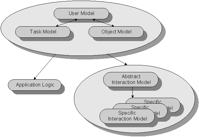
Our model-based approach TADEUS [3] is based on user, task and business-object models. It allows the computer based development of interactive systems. The three models are the basis for the development of the application logic and the user interface design. Figure1 represents the main relations between different models.

Fig. 1. Model-Based User Interface Design
This approach allows a reuse of the designed models apart from final representations. To have a flexible development process from an abstract interaction model to a specific representation there was the idea to use the XML technology [9] for representation and transformation features.
2. Related Work in Specifying User Interfaces by XML
There are already some approaches to specify user interfaces by markup languages. There is for instance UIML [1] a XML-based language for describing user interfaces. It comes with different rendering programs allowing the generation of user interfaces on different platforms. Up to now the generation for WML, Java AWT and swing are available.
A special renderer for each target-device is needed. This is an important disadvantage The flexibility for selecting target-device features is limited because of a lack of a mapping concept.
XUL has its focus on window-based graphical user interfaces by XML. Its disadvantage is the limitation to such graphical user interfaces. It is not applicable to interfaces of small mobile devices.
There is no abstraction of interaction functionality available. The device-independent specification of user interfaces was not planned.
3. Specification of User Interfaces
A user interface is considered as a simplified version of the MVC model and is separated into a model component and a presentation component.
The model component describes the feature of the user interface on an abstract level. It is also called abstract interaction model.
The user-interface objects with their representation are specified in the presentation component. During the development a mapping transforming the abstract interaction model to the specific interaction model is necessary. TADEUS use a term representation of both models. The transformation process is described by attribute grammars. For different platforms different grammars are necessary. The development of such grammars for different mobile devices is time consuming. It would be good to have more support for the transformation process. Especially the integration of the specific features of different devices is difficult. A general support would be appreciated.
The XML technology [9] offers such an opportunity. It allows the description of the abstract interaction model, the description of specific characteristics of different devices and the specification of the transformation process, which will be shown later.
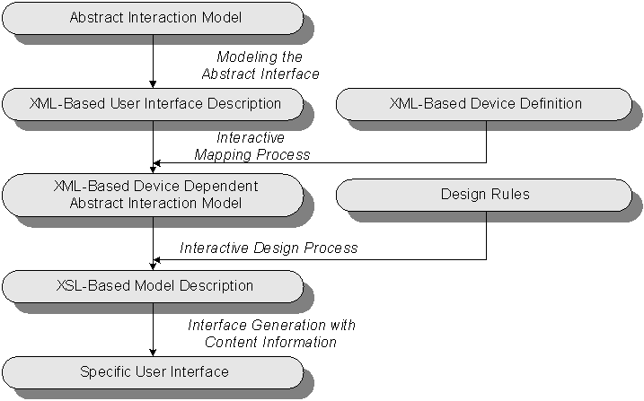
User, tasks and object models are a good starting point for developing a user interface but it is not necessary to specify them explicitly. Let us have a look at a model of the transformation process forming an abstract interaction model to a specific user interface:

Fig. 2.
Creation of a User InterfaceFollowing requirements should be fulfilled by a markup language specifying user interfaces:
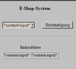
The following paragraphs will show a specific way of using XML in the proposed manner. The example of an e-shop will be used to show the principles of this approach. The transformation from an abstract specification to a concrete user interfaces will be shown. If the reader wants to get a visual impression of the shop he may have a look at the example in figure 3.
3.1 XML-Based Abstract Interaction Model
The abstract interaction model is transformed into a notation which is based on a language of the XML family. The basic document type definition (DTD) for an example has the following form:
<?xml version="1.0" encoding="ISO-8859-1"?>
<!-- version 0.5 14.02.2001 -->
<!--MARK 1 -->
<!ELEMENT ui (uio+, context*)>
<!ATTLIST ui ui_name CDATA #REQUIRED>
<!ELEMENT uio (uio | ((output+, context*)* , (input+, context*)*))>
<!ATTLIST uio name CDATA #REQUIRED>
<!--MARK 2 -->
<!ELEMENT context (context_value+)>
<!ELEMENT context_value (#PCDATA)>
<!ELEMENT output ((output_string | output_1-n | output_m-n | output_table), context*, optional?)>
<!ATTLIST output name CDATA #REQUIRED> . . . .
<!ELEMENT output_table (#PCDATA)>
<!ATTLIST output_table num_x CDATA #IMPLIED
num_y CDATA #IMPLIED>
<!ELEMENT input ((input_1-n | input_m-n | input_trigger |input_string | input_table), context*, optional?)>
<!ATTLIST input name CDATA #REQUIRED>
<!--MARK 3 -->
<!ELEMENT input_1-n (#PCDATA)>
<!ATTLIST input_1-n range_min CDATA #IMPLIED
range_max CDATA #IMPLIED
range_interval CDATA #IMPLIED
list_n CDATA #IMPLIED>
<!--MARK 4 --> . . . .
<!ELEMENT input_table (#PCDATA)>
<!ATTLIST input_table num_x CDATA #IMPLIED
num_y CDATA #IMPLIED>
<!ELEMENT optional (optional_value+)> . . . .
Example 1: DTD for user interface description
This example includes some marks (e.g.
<!-- MARK 1 --> ) to support the explanation in the following text. A user interface is at this stage composed of one or more user interface objects (UIO). A UIO can be composed of other UIOs or one or more input-/output values (Mark 1-2). These values are in an abstract form and describe interaction features of the user interface in an abstract way. Later there will be a mapping process of these abstract UIOs to concrete ones. Between Mark 2-3 you can see different types of these abstract UIOs. They have different attributes to specify their behaviour. One example to explain is the input_1-n value (Mark 3-4). Here we have some attributes to specify these abstract UIO. The input_1-n value for instance can be mapped to a slider as a concrete UIO. The range_min attribute specify the minimum-value of input possibilities, the range_max attribute specify the maximum-value. The range_interval value is for fixing the interval within the range. Also we can specify a list of input values.Now lets have a look at an example of a simple user interface of a little e-shop system:
<?xml version="1.0" encoding="ISO-8859-1"?> . . . .
<ui ui_name="e-shop">
<uio name="title"> . . . .
<output name="title">
<output_string/>
</output>
</uio> . . . .
<uio name="Art_group">
<input name="Art_group">
<input_1-n/>
</input>
</uio> . . . .
<uio name="Article">
<output name="Art_Name">
<output_string/>
</output> . . . .
<input name="Order">
<input_trigger/>
</input>
</uio> . . . .
</ui>
Example 2: Description of a simple user interface of an e-shop system
Because of a lack of space only a few attributes are mentioned here. But it seems to be clear how such a specification looks like.
3.2 XML-Based Device Definition
A universal description language for describing properties of various target devices in abstract and comparable matter is necessary to support the transformation process from an abstract interaction model to a device dependent abstract interaction model. Based on [16] such a language was developed. Specifications written in this language are XML documents describing the specific features of devices. Let us have a look at the corresponded DTD.
<?xml version="1.0" encoding="ISO-8859-1"?>
<!-- DevDef-File Version 0.2 Date: 01.02.2001 -->
<!ELEMENT device (device*, service*, vendor, version)>
<!ATTLIST device id ID #REQUIRED>
<!ELEMENT service (name+, feature+, service*)>
<!ATTLIST service kind CDATA #REQUIRED>
<!ELEMENT name (#PCDATA)>
<!ATTLIST name language CDATA #REQUIRED>
<!ELEMENT feature (description)>
<!ATTLIST feature id ID #IMPLIED>
<!ELEMENT description (text+, value, property)>
<!ELEMENT property (#PCDATA)>
<!ELEMENT value (#PCDATA)>
<!ELEMENT vendor (url*, text)>
<!ELEMENT url EMPTY>
<!ATTLIST url ref NMTOKEN #REQUIRED>
<!ELEMENT version (#PCDATA)>
<!ELEMENT text (#PCDATA)>
Example 3: DTD for Device Definition
The specifications are not only necessary for this transformation they influence the specification of formatting rules as well.
Following example shows a very short fragment of a device definition of java.AWT:
<?xml version="1.0" encoding="ISO-8859-1"?>
<?xml-stylesheet type="text/xsl" href="?.xsl"?>
<!DOCTYPE device SYSTEM "devdef-1.dtd">
<device id="Advanced Windowing Toolkit">
<device id="java.awt.Button">
<service id="?" kind="trigger">
<name>Location</name>
<feature>java.awt.Button.setLocation</feature>
</service>
</device>
<vendor>SUN Microsystems</vendor>
<version>2.0</vendor>
</device>
Example 4: Device definition for java.AWT
3.3 XML-Based Device Dependent Abstract Interaction Model
This model is still on an abstract level but it fulfils already some constraints coming from the device specification. It uses available features and omits not available services. The result of the mapping process is a file in which all abstract UIO's are mapped to concrete UIO's of a specific representation. The structure of this file is based on a XML-DTD which was introduced as follow:
<?xml version="1.0" encoding="ISO-8859-1"?>
<!-- UI-Mapping-File Version 0.3 Date: 30.01.2001 -->
<!ELEMENT ui_map (class, device*, uio+, context?)>
<!ATTLIST ui_map
uim_name CDATA #REQUIRED>
<!ELEMENT class (UID, target)>
<!ELEMENT UID (#PCDATA)>
<!ELEMENT target (#PCDATA)>
<!ATTLIST target
version CDATA #IMPLIED>
<!ELEMENT device (device | (type, parameter+))>
<!ELEMENT type (#PCDATA)>
<!ELEMENT parameter (text?, option, value)>
<!ELEMENT text (#PCDATA)>
<!ELEMENT option (#PCDATA)>
<!ELEMENT value (#PCDATA)>
<!ELEMENT uio (uio | ((output*), (input*)))>
<!ATTLIST uio
name CDATA #REQUIRED>
<!ELEMENT output ((output_string | output_1-n | output_m-n |
output_table), device+, optional?)>
<!ATTLIST output
name CDATA #REQUIRED . . . .>
<!ELEMENT output_string (#PCDATA)> . . . .
<!ELEMENT input ((input_1-n | input_m-n | input_trigger |
input_string | input_table), device+, optional?)>
<!ATTLIST input
name CDATA #REQUIRED . . . .>
<!ELEMENT input_string (#PCDATA)> . . . .
<!ELEMENT context (context_value+)>
<!ELEMENT context_value (#PCDATA)>
<!ELEMENT optional (optional_value+)>
<!ELEMENT optional_value (#PCDATA)>
<!ATTLIST optional_value
name CDATA #REQUIRED
value CDATA #REQUIRED>
Example 5: DTD for UIO-Mapping
This file is specific according to a target device and includes all typical design properties of concrete UIO's like colour, position, size etc. It is a collection of option-value pairs where the content of the values specified later on in the design process and describes a "skeleton" of a representation of a specific user interface. The user interface is designed on the basis of this skeleton during the following design process by designers or ergonomics.
Our simple example of an e-shop system mapped as a HTML-representation looks like follow:
<?xml version="1.0" encoding="ISO-8859-1"?>
<?xml-stylesheet type="text/xsl" href="?.xsl"?>
<!DOCTYPE ui_map SYSTEM "uim-1.dtd">
<ui_map uim_name="e-shop-html">
<uio name="Title">
<output name="Title">
<output_string/>
<device>
<type>H3</type>
<parameter>
<option></option>
<value></value>
</parameter> . . . .
</device>
</output>
</uio> . . . .
<uio name="Art_Group">
<input name="Group">
<input_1-n/>
<device>
<type>SELECT</type>
<parameter>
<option>SIZE</option>
<value>1</value>
</parameter>
<parameter>
<option>OPTION</option>
<value></value>
</parameter>. . . .
</device>
</input>
</uio> . . . .
<uio name="Ok">
<input name="Ok">
<input_trigger/>
<device>
<type>BUTTON</type>
<parameter>
<option>TYPE</option>
<value>submit</value>
</parameter> . . . .
</device> . . . .
</uio> . . . .
</ui_map>
Example 6: E-shop abstract user interface mapped to abstract device dependent (HTML) interaction model
The same user interface mapped as a java.AWT looks like introduced in the next example:
<?xml version="1.0" encoding="ISO-8859-1"?>
<?xml-stylesheet type="text/xsl" href="?.xsl"?>
<!DOCTYPE ui_map SYSTEM "uim-1.dtd">
<ui_map uim_name="e-shop-awt">
<uio name="Title">
<output name="Title">
<output_string/>
<device>
<type>java.awt.Label</type>
<parameter>
<option>java.awt.Label.setLocation</option>
<value></value>
</parameter>
<parameter>
<option>java.awt.Label.setSize</option>
<value></value>
</parameter> . . . .
</device>
</output>
</uio> . . . .
<uio name="Art_Group">
<input name="Group">
<input_1-n/>
<device>
<type>java.awt.Choice</type>
<parameter>
<option>java.awt.Choice.setLocation</option>
<value></value>
</parameter> . . . .
</device>
</input>
</uio> . . . .
<uio name="Ok">
<input name="Ok">
<input_trigger/>
<device>
<type>java.awt.Button</type>
<parameter>
<option>java.awt.Button.setLocation</option>
<value></value>
</parameter> . . . .
</device> . . . .
</uio> . . . .
</ui_map>
Example 7: E-shop abstract user interface mapped to abstract device dependent (java.AWT) interaction model
We demonstrate the HTML and java.AWT dependent generation. The wml-example is omitted because of its similarity to the HTML document.
3.4 XSL-Based Model Description
The creation of the XSL-based model description is based on the knowledge of available UIOs for specific representations. It is necessary to know which values of properties of a UIO are available in the given context. The XML-based device dependent abstract interaction model (skeleton) and available values of properties are used to create a XSL-based model description specifying a complete user interface. The HTML-based e-shop example looks like follow:
<?xml version="1.0"?>
<xsl:stylesheet xmlns:xsl="http://www.w3.org/XSL/Transform/1.0">
<xsl:output method= "html"
xml-declaration="yes"/>
<html> . . . .
<h3> E-Shop-System </h3>
<br/>
<SELECT size=1>
<option>"content-input" </option>
<option>"content-input" </option> . . . .
</SELECT>
<br/> . . . .
<BUTTON type=submit>Ok</BUTTON>
<br/> . . . .
<TABLE>
<CAPTION>purchase list</CAPTION>
<TR>
<TD>"content-input"</TD>
<TD>"content-input"</TD>
</TR> . . . .
</TABLE>
</html>
</xsl:stylesheet>
Example 8: XSL-file for generation of a HTML user interface of the e-shop
The wildcard "content-input" shall symbolise a content handling from applications or databases in a later step of development.
3.5 Specific User Interface
By XSL transformation a file describing a specific user interface will be generated. Examples for java.AWT and HTML are given in [1]. Unpublished WML examples were developed as well.
The XSL transformation process consists of two sub-processes:
The generated model is already a specification runable on the target platform. It is constructed by a transformation process which uses the device dependent abstract interaction model as input, which is coded in XML.
There are two different cases. The user interface is generated once like for java.AWT or it has to be generated dynamically several times like for WML. In the first case there is no need for a new generation of the user interface if the contents changes. The content handling is handled within the generated description file.
In the second case the content will be handled by instructions within the XSL-based model description. Each modification of the contents results in a new generation of the generated description file.


Fig. 3: Resulting user interfaces HTML and WML
4. Results and Future Work
The current work includes the specification of XML-based languages describing different abstraction of a user interface for mobile devices. A concept for the mapping process from abstract UIO's to concrete UIO's was developed. A XML language was developed which allows the specification of the features of the user interface of mobile devices. The transformation process of the user interface is based on specifications written in this language. In an interactive design process based on an abstract device dependent abstract interaction model and some design rules a more refined xsl-description of the user interfaces is developed, which allows the generation of specific user interfaces.
This concept is already evaluated by several examples. A tool supporting the mapping and design process is under development. A first prototype is already available, which delivers already promising results. Up to now this tool is not integrated in previous phases of the design process. The abstract interaction model has to be edited manually. This will be omitted in the near future.
Our experiments show that XML is a promising technology for the platform independent generation of user interfaces.
Further studies will demonstrate whether dialogue sequences of already developed applications can be integrated into the design process. Such patterns of already developed user interfaces could extremely enhance the development process. The most important results of this research will be the way to find and to integrate such patterns.
References